Share
Pin
Tweet
Send
Share
Send
Simple flasher diagram on NE555
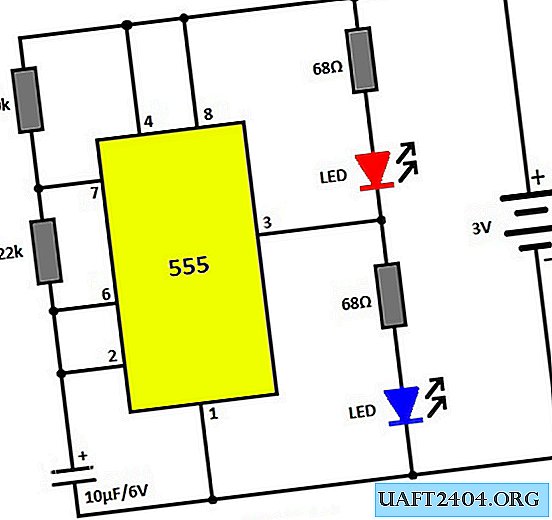
A multivibrator is built on the microcircuit, which generates rectangular pulses. The length of these pulses can be changed by selecting a capacitor of 10 μF resistor 220 kOhm. The circuit uses two LEDs that turn on alternately. But if you want to use only one LED, then the second one can simply not be included in the circuit - this will not affect the performance of the entire device.
The circuit is powered from 3 V, but the power can be in the range of 3-15 V, the microcircuit allows this, only when changing the power upward, it will be necessary to select resistors in the LED circuit. If you feed the flasher from 12 V, then replace the resistors with 1.5-2 kOhm.

After assembly, the flasher does not need to be configured and starts flashing immediately after switching on. Instead of a 220 kOhm resistor, you can solder a variable or tuning resistor to adjust the desired blinking frequency for the LED.

I tore off the circuit on the breadboard. Also, due to the minimum components, the entire device can be assembled by hinged installation and pour hot glue. I used this scheme in my car, I am satisfied with the result, everything is working stably to this day.
Watch the video of the assembly and operation of the emergency light on the NE555
Share
Pin
Tweet
Send
Share
Send