Share
Pin
Tweet
Send
Share
Send
But it is possible to make this grinding machine yourself in a home workshop without the high cost and, at the same time, compact size, based on a standard grinder.
It should be noted that the work will require us some time, certain skills, preparation of materials, equipment and tools.
Will need
For the manufacture of homemade goods, we will need completely affordable and inexpensive materials:
- different metal (corner, profile pipe, strip);
- threaded parts (nuts, washers, screws, bolts, studs);
- tension and compression springs;
- plastic head bolt;
- sleeves cable aluminum;
- bearings;
- enamel on rust.
Some operations can be performed manually, but the work will go faster and easier, if available:
- grinder with a cutting disc;
- drilling machine;
- welding equipment;
- drill with drill and countersink;
- square and pencil;
- vernier caliper and tape measure;
- core and hammer;
- file for metal;
- tap, screwdriver and wrenches.
Technology for manufacturing grinder from angle grinders
Our homemade product will consist of three main components:
- power frame (frame);
- drive (grinder);
- tension roller system;
It is better to prepare in advance, if not drawings, then at least calculations of the main dimensions. With the help of measuring devices, we will transfer them to the workpieces and only after that we will begin cutting.
We weld the frame of the machine from a square pipe.

One of the elements will be made of a steel equal-angle corner, which, after marking, cuts and drilling, will be a node with equal cutouts along the edges of one shelf, and in the remaining part, two equal holes are made closer to the adjacent shelf and its edges. Later this unit will be further developed.

Taking the above assembly as a template, mark out a smaller, equal-angle steel corner, attaching it to a shortened shelf and aligning their centers. We transfer the centers of two holes to one of the shelves of a smaller corner. At the edges, we outline two more holes equally spaced from the ends. Then, according to the marking, we drill 4 holes, removing burrs from all holes.
We finish the assembly made from a large corner: we cut the grooves from the edge of the shelf to the holes whose width is equal to the diameter with a cutting disc, remove the burrs and round off the edges with a file.

Using a welding template, we weld a small corner with four holes with another shelf symmetrically to the end of the section of the profile pipe - the frame element.
We assemble the nodes of the base in the desired order and weld together.

We mark the metal strip, commensurate with the length of one part of the element (12 cm), made from a small corner. In the upper inner corner of the frame we have an elongated nut, which will then be welded.
We put a strip under the frame so that it is parallel to the small corner and protrudes 12 cm beyond the longitudinal frame element. We mark the drilling site on the strip along the nut, make a hole and cut the thread in it with a tap. Weld the nut in place.

We fasten the strip with the hole to the nut with a bolt and install it at an angle of 45 degrees to adjacent frame elements.

In this position, draw a line on the strip using the outer edge of the vertical frame element and cut it according to the marking. To the frame element, in place we weld a limiter for a lever with an oblique cut. We process the circular arm on a grindstone.


From the remainder of the strip, we cut off a fragment with a height slightly less than its width and perform a symmetrical recess in it from a smaller end. Using this detail as a template, we cut a fragment slightly longer from the strip, but with the corresponding spike.
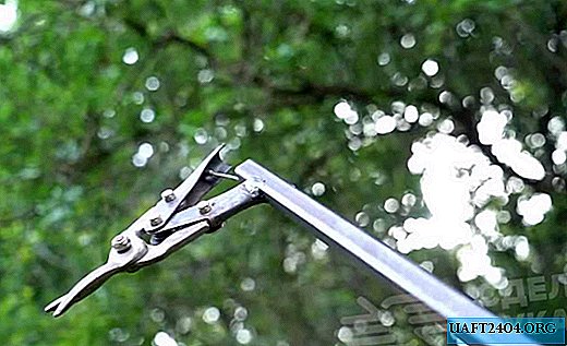
We connect these two elements so that they can freely rotate relative to each other due to one axis passing through the through hole in two protrusions and one spike.

In the flat end of the lever, we drill two holes and cut the threads into them. We fix the movable unit with two screws to the end of the lever, and the entire system with a bolt to the nut welded to the frame.


Closer to the sharp end of the lever and in the vertical frame element opposite, drill holes and fix bolts with nuts in it. We connect a spring to them to hold the lever in the extreme position.

We drill holes in the lever and the movable element, and then cut the threads into them.

We cut two identical fragments from a thick metal strip. We perform holes in them along the edges and weld to the frame for stability or attachment to another base.

We fix the bolts with nuts in the extreme holes in the element from the corner. In the hole of the movable "tongue" on the lever with a nut we fix the pin.

Insert and fasten the shorter bolts into the two central holes. We put washers on top of the nuts, on the outside, using slots, install an element made of a large corner, and tighten it with nuts.

We put a spring and a washer on a bolt with a plastic head and screw it, compressing the spring, into the threaded hole in the movable lever so that the end of the bolt rests on the "tongue" and can be rejected if necessary.

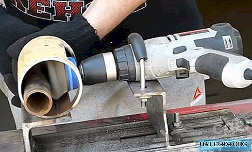
From aluminum cable sleeves we make three identical tubes and one slightly longer. We press one bearing into the prepared tubes into the prepared sockets, and into the long one - the hexagonal elongated nut using a screw press.
We install washers on the rods of the three bolts, and then the tubes with bearings pressed into them, fixing them with nuts.
With a metal ruler, set the outer side of the element shelf from a large corner to a plane with tubes at the ends of the element from a smaller corner, and tighten it in this position with nuts.

Four fragments of the same length are cut out from a metal strip of the desired width and two more - one shorter and the other longer. From them we form a knot for mounting the grinder with the possibility of changing its position in two planes.


The mounting unit of the grinder, in turn, will be attached to the base of the frame with two bolts welded to it in advance.
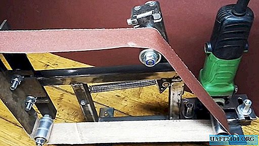
We install the grinder in place, and on the spindle we screw an aluminum tube with a nut pressed into it.

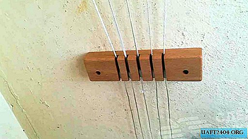
We put in place the spring of the movable lever and put on the aluminum rollers an annular tape from a strip of sandpaper. To do this, overcoming the spring force, we shift the tension roller towards the follower, and after installing the tape on the rollers, release it to create an interference force.
Turn on the grinder and watch the tape. If it is shifted to the side, then rotating the screw head, we change the position of the axis of the adjustment roller and parry the tape offset.
It remains only from the side of the working branch of the emery tape to set the working table using the adjustable console mounted on the frame.


To give the device aesthetics, it can be disassembled and painted parts with enamel on rust, and then reassembled.

Share
Pin
Tweet
Send
Share
Send