Share
Pin
Tweet
Send
Share
Send
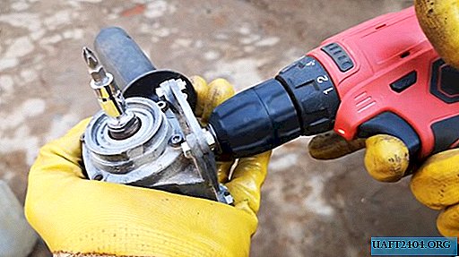
Any instrument has its own deadline. But this does not mean that it needs to be thrown into the landfill, because some of its parts can still be used. For example, as in today's case with a failed grinder (angle grinder). Let's try to make an interesting device for a screwdriver out of it.

For this homemade product, we need only the gear part from this power tool. This part is removable in most grinders, and even sometimes remains “alive” after their final use. It is important for us that the gear case is intact, the bearing and chassis are working, without slipping or, even worse, jamming. A small length of shaft mounted on the rotor will also be needed. Well, let's get started?
Turn the angle grinder into a tool
The first step is to separate the gearbox from the rest of the grinder body. It is not difficult to do this, usually it is square in shape and fastened at the corners to the screws. Perhaps for this compartment it will be necessary to begin dismantling the electrical part of the tool, remove the brushes, the start button, and then the rotor with the shaft and gearbox.

The gearbox needs to be fully revised. We disassemble it completely, removing all retaining rings and gaskets. If necessary, replace the bearing, it most often fails in this tool. This is due to the actuation of metal elements at high speeds, and the ingress of microparticles into the lubricant, and then into the bearing housing.
Two elements participate in this gear angular transmission - the driving gear (small, located on the shaft) and the driven gear (wider, located in the gearbox itself). Due to the difference in the number of teeth, the gear ratio is set, and the speed of rotation of the gearbox shaft is adjusted. Dismantle the drive gear by unscrewing the nut on the rotor shaft with a suitable wrench.
For the operation of our device you will need a segment of the shaft, 7-8cm long. It may be necessary to cut off a part of the rotor housing.


When all the components are ready, you can start assembling the gearbox with a segment of the rotor shaft. We put the pinion gear in its place on the rotor shaft, and press it with a wrench.

We connect the air separation gasket and the gear housing to four screws, which are then cut flush to the nuts along the length.

The outgoing section of the rotor shaft must be modified. Clamp the gearbox in a vice, and fix the shaft with a clamp. The rotor shaft, in turn, is triggered by a grinder under the shape of the tetrahedron. This is most conveniently done with a grinding disc. With a caliper, do not forget to measure the accuracy of a size that corresponds to 6.5 or 9.5 mm (depending on the mounting size of the screw heads).


Important! The more uniformly the shaft is polished, the more accurately its center of rotation will be located, which means that the play during rotation of the tool will be minimal.
The gearbox nozzle is ready, it remains to clamp the rotor shaft into a screwdriver or drill, and check it in action. The tip of this device, namely the gearbox shaft, allows you to use it as a wrench or a device for twisting screws, screws. It can be used in hard-to-reach places where the body of a conventional tool does not allow this. So, it’s practical, cheap and easy!


Some practical tips
Of course, such a device cannot be made manually. For work, you will need a grinder (working!) With a cutting and grinding discs, screwdrivers, pliers, pliers for lock rings and terminals, a hammer and wrenches. It may be necessary to remove the bearing puller.
And yet, when assembling the gearbox, do not forget to fill it with grease, as manufacturers of grinders do. This will extend the life of your instrument. And at the right time, he will help you out, because as you know, the road is a spoon for dinner!


Share
Pin
Tweet
Send
Share
Send


