Share
Pin
Tweet
Send
Share
Send
On the Internet there are many different schemes of LED flashing lights - simple, complex, with and without microcircuits. But now you won’t surprise anyone with an ordinary flashing LED, so there is a need to assemble something more advanced. For example, an acoustic flasher - a microphone picks up sound and turns it into flashes of LEDs. The scheme is presented below.
Scheme

On the circuit there is an electret microphone, which turns sound vibrations into electrical ones. You can find it in broken phone headsets, or in the radio parts store. Transistors T1 and T2 amplify the signal so that it is enough to ignite the LEDs. You can use almost any low-power n-p-n transistors, for example, BC547, KT315, KT3102. LEDs are used ordinary 3-volt of any color, you can put two pieces, as indicated in the diagram, or more. Capacitor C1 is used to suppress ripple power, its capacity can lie in the range of 10-100 microfarads. The supply voltage of the circuit is from 3 to 5 volts.
svetodiodnaja-akusticheskaja-migalka.zip 20.81 Kb (downloads: 648)

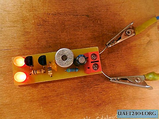
Flasher assembly
The circuit is assembled on a miniature printed circuit board measuring 45 x 15 mm, which can be done by the LUT method. The printed circuit board is completely ready for printing, you do not need to mirror it. Please note that the board is designed for the installation of BC547 transistors, when using similar transistors with a different pinout, you will have to swap their outputs on the board. Below are some photos of the board manufacturing process.


It is desirable to tear the tracks, this will protect the copper from oxidation and facilitate the further soldering of parts. First of all, small parts are installed on the board - resistors, transistors, and only then capacitors and LEDs. To connect the power wires, it is most convenient to use a screw terminal block. When installing a microphone, it is necessary to observe its polarity - the minus leg of the microphone is connected to its metal body, it must be soldered to the minus circuit. After assembly is complete, the flux residues must be washed off the board and the installation correct.


Setup and testing
We supply power to the board and look at the reaction of the LEDs - they must be completely extinguished in the absence of sound. If the LEDs are lit continuously, then you need to increase the resistance of resistors R2 and R3 by a factor of 1.5 - 2, until the LEDs turn off, this is the only setting for the circuit. After that, the LEDs will flash instantly if any sound, clap, click, or even music is heard nearby. When using a sensitive microphone, the sound detection range is approximately 6-7 meters. The circuit will be a great toy for children - after all, watching how the LEDs light up at the slightest sound is quite exciting. Also, the circuit can be used to test the sensitivity of electret microphones. Successful assembly.
Share
Pin
Tweet
Send
Share
Send