Share
Pin
Tweet
Send
Share
Send
This is a good and low-cost way to make an adjustable power supply without much cost and effort. For example, I have a good power supply unit for 12 V and 2 A. I will assemble a prefix for it, with which it will be possible to regulate the voltage over a wide range. Everything will be built on ready-made Chinese modules, I just have to make a case for the device and connect all the wires.
Necessary materials
Parts List (purchase links):
- - Amp Voltmeter Module.
- - DC-DC buck converter.
- - Variable resistor at 10 kOhm.
- - Terminals 2 pcs.
- - Wires.
- - A socket for connecting the power supply.
- Plywood for the housing.
- Reiki for the case.
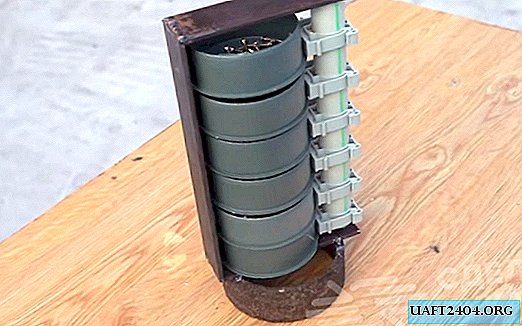
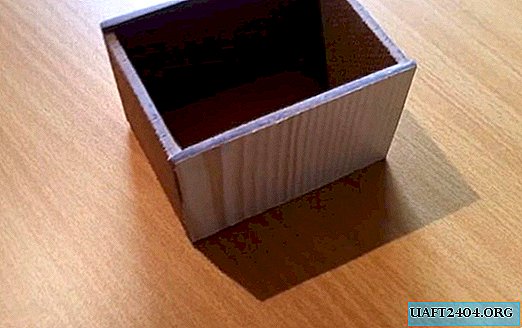
Preparation of regulator housing parts
We burden plywood and cut out parts of the body. You’ll guess the dimensions yourself so that everything comes in. Of course, you can take the finished building and skip these steps, but I'm collecting a budget regulator.


We smear the ends with glue on the wood and clamp everything with a clamp. We wait until the glue dries.

Body assembly
The front and back panels will be made of plastic, as it is easier to handle and looks more solid.


I glued the racks into the corners of the rails for rigidity of all structures.

We clean the ledges.

The housing is ready.

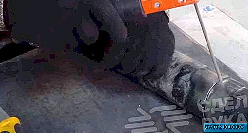
Modification of the buck converter
This is a buck converter. Up to 30 V can be supplied to it and it will be regulated without any problems. The load current is 1.5 A. And without radiators, there is built-in protection against overheating. Since it is pulsed it has a very high efficiency. Plus, the output voltage is perfectly stable.

All its refinement comes down to replacing the tuning resistor on the board with a remote variable.

We solder the tuning resistor.

We solder a variable resistor on the wires.


That's the whole revision.
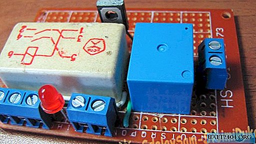
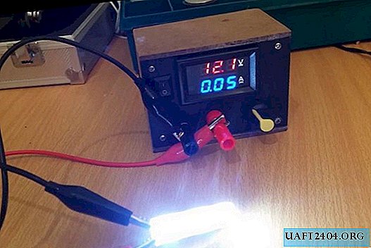
Controller circuit assembly
Here is the inclusion circuit itself.

Putting the circuit together.

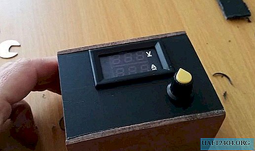
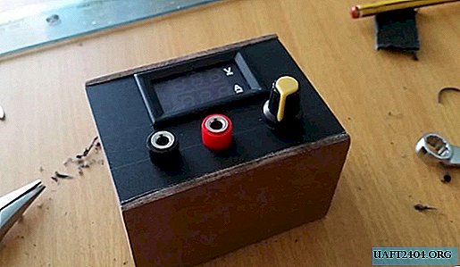
Everything is working. The ampervoltmeter perfectly displays voltage and current.
Regulator assembly
We cut the ammeter into the front panel. We drill holes for the connectors and a variable resistor. We insert everything and the front part is ready. We fix the panel.


We connect all the parts. We fix the connector for the input of the power supply to the back wall.


We put the module on hot glue so that it does not hang inside.


Everything is ready. But I forgot to say that just in case I added a switch. It is not needed, but suddenly I want to connect the console to the battery.

The last step is to tighten the screws on the front and rear panels.

Voltage Regulator Test
We connect the power supply to the connector. We connect the load. Everything works in astonishment! The adjustment is smooth.


Of course, a voltmeter with an ammeter could not be set, but how could it be without it.
Watch the video of making and checking a simple regulator
Share
Pin
Tweet
Send
Share
Send