Share
Pin
Tweet
Send
Share
Send
I bring to your attention a bug scheme that can be assembled by both an experienced radio amateur and a beginner in this matter.
Let's look at this scheme:
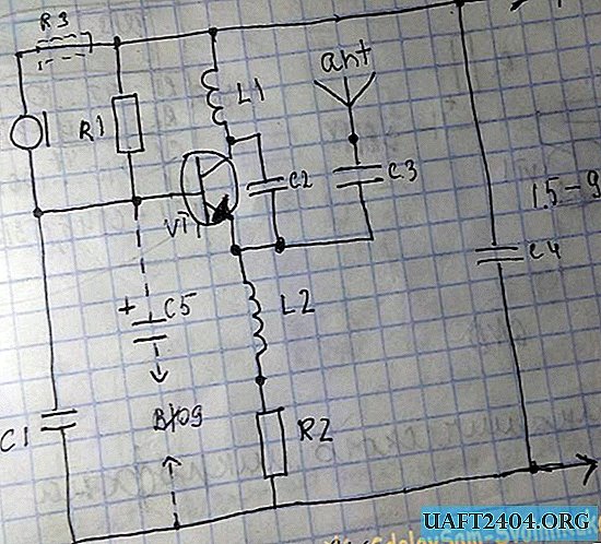
For a dotted line do not pay attention yet.
To make a bug, we need the following details:
- VT1 - kt315 with any letter index (if you want to increase the range of the bug, it is better to use a microwave transistor, for example kt325 or kt368, the imported transistor s9018 is perfect);
- C1, C4 - 47 ... 68nf;
- C2, C3 - 10pF;
- R1 - 33 kOhm;
- R2 - 100 ohms;
- Oscillating circuit L1 - 8 turns of copper wire with a diameter of 0.3 ... 0.5 mm on the rod from the helium pen, wind carefully, turn to turn (I unsoldered the finished coil from a broken radio).
- M1 - electret or condenser microphone.

In order to save space, I used the right microphone (found it in an old mobile phone). Despite its size, it turned out to be very sensitive.
All details except the L2 throttle and microphone are shown in the following picture:

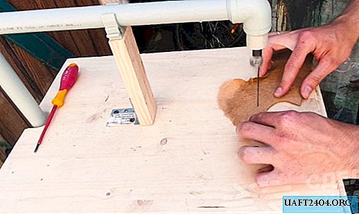
To make L2, we need a match and a very thin wire:

We measure one and a half centimeters of a match, bite them off - this piece will serve as the core of the throttle. Next, take the wire and wind one hundred turns. We fix the conclusions of the resulting coil, clear of varnish, tin. That's it, the L2 throttle is ready!

When all the parts are assembled, you can begin to manufacture the printed circuit board.
To do this, we need a piece of PCB 35x15mm and the solution itself, in which we will etch the board (I used hydrogen peroxide + citric acid). We make a drawing of the printed circuit board (I painted under the s9018 transistor)

and transfer it to the textolite.

We put the board in the solution and wait until the excess copper disappears.
After the board is comfortable, we take it out, rinse it with running water, remove the varnish and tack it:

Next, solder the parts in accordance with the scheme. Attention, when mounting parts on the board, do not overheat them, otherwise they will fail! Take particular care in mounting the VT1.
I want to say a few words about connecting the antenna, the signal to it is supplied from the emitter of the transistor, which makes the working frequency of the bug more stable.
Assembled circuit:


The bug can be fed in the range from 1.5 to 9 volts.

Any of these batteries are suitable for powering the circuit. I used a AAA finger-type battery for a more compact bug. You can also use a 3-volt "pill".
If you will feed the circuit from the crown (9 volts), then you should include in the circuit a resistor R3 with a nominal value of 100 Ohms.
Gently solder the battery to the bug. As an antenna, you can use an insulated wire 30 cm long, but practice has shown that its absence will not greatly affect the reception range of the circuit. Everything, the bug is ready!

Now turn on the radio and look for the frequency of our bug. The signal from it can be caught at a frequency in the range of 88-108 MHz. My frequency was 92.2 MHz. If the bug “doesn’t get in touch”, then try to expand the turns of the L1 coil - this should help solve the problem.
With a supply voltage of 1.5 volts, the reception range is 30 meters, if you increase the voltage to 3 volts, then the reception range will increase to 100 meters.
This circuit also has another application - an audio transmitter. Suppose you need to output sound from a telephone to a tape recorder, but the latter does not have an audio input function. No problem! In this situation, this scheme is very useful. Almost all tape recorders have a radio reception function (FM radio), which we will use. Remember the dotted line in the bug diagram? We exclude the M1 microphone from the circuit, connect the C5 capacitor to a capacity of 10 microfarads, connect the 3.5mm “mini-jack” plug to the minus of the capacitor and the power minus (minus the “jack” to the general, left / right to the minus the capacitor) and transfer the sound from the phone to any a radio located in the range of the transmitter! With proper installation of parts, the circuit starts working immediately.
You can use these products for a variety of purposes: from listening to rooms to wireless sound transmission.
And on this my article comes to an end, good luck to everyone in repeating!
Share
Pin
Tweet
Send
Share
Send